Experiment 4: DHCP, NAT and Firewall
Objectives
Practice a more advanced router configuration using a web interface
Observe traffic for the DHCP
Observe how a firewall and NAT works
Configure port forwarding
References
UltraVNC: https://uvnc.com/
ip command overview and examples: https://www.cyberciti.biz/faq/linux-ip-command-examples-usage-syntax/
OpenWrt documentation: https://openwrt.org/docs/start
Wireshark: https://www.wireshark.org/
Background
Before performing this experiment, review the following topics: LANs, DHCP, NAT.
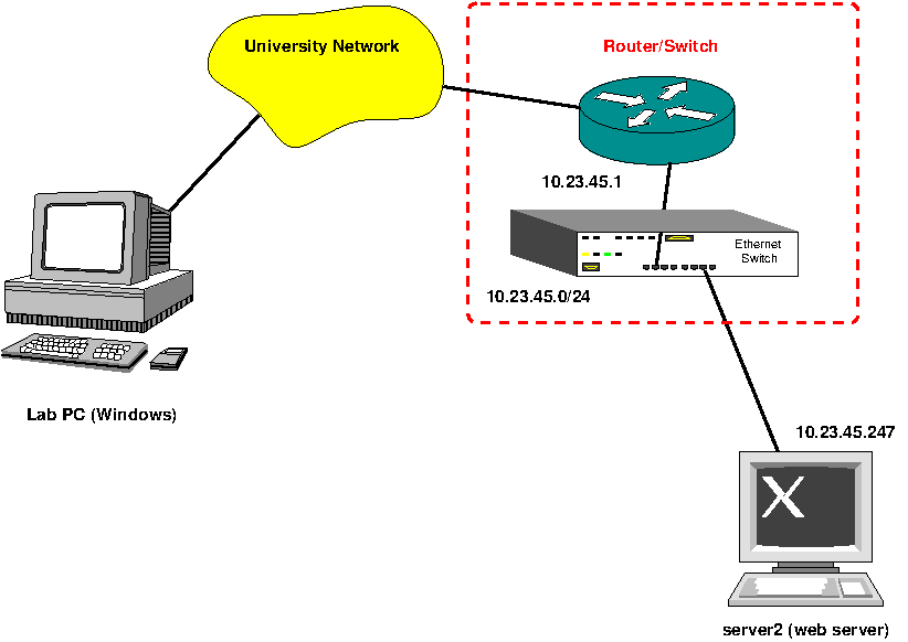
The network topology is shown below. In this case, there is an external connection to Internet and the router will perform NAT. IP addresses in the figure are just illustrative values: actual values for the experiment will depend on the group number and the organization ID assigned by the lab instructor. The router has two IP addresses, one for the private LAN and another for the university network.

Procedure
Ask the lab instructor to be assigned a group number, a virtual LAN network ID, and the port numbers to connect to web server console (server2) for this experiment. In this manual, we’ll assume that the data provided is the following:
Private LAN ID: 10.23.45.0/24
Port for server2 workstation (AKA web server): 11001
VNC password and account information for server2 and router administrator password
Launch UltraVNC and connect to the server2 console. The addresses to connect should look similar to the following:
2453server.lakeheadu.ca:11001
For this experiment, the server is configured with a graphical interface to allow us to configure the router and observe captured packets. We’ll have no console access to the router. Instead, we’ll use a web interface to configure it.
Login into server2 and open a terminal. Only the loopback interface is configured initially. The Ethernet interface is named
enp7s0(check the name you get, it may be different). There is no active connection to other computers in the network. By default, the router is configured with a DHCP server for an internal private network of 192.168.1.0/24. The router interface is assigned 192.168.1.1. Initially, we need to use that network since we are going to configure the router through a web interface. To manually request an IP address to the DHCP server, execute the following command (seeman dhclientfor details):user@server2:~$ sudo dhclient -v
Open a web browser and connect to
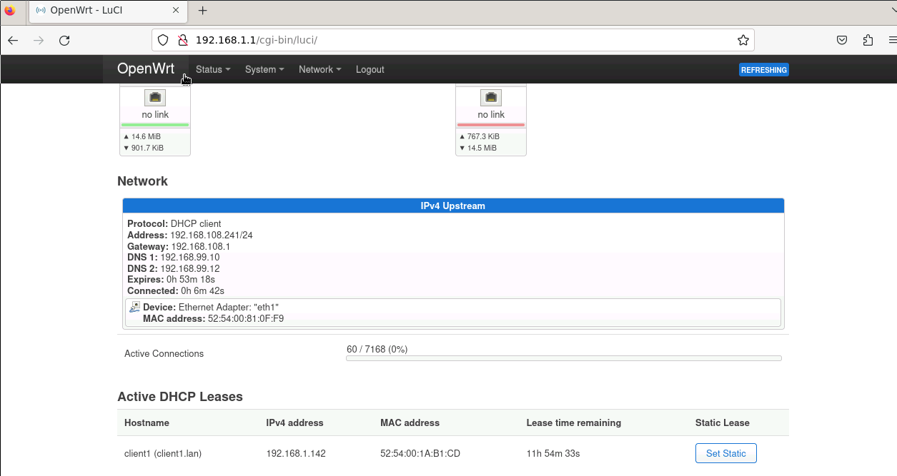
http://192.168.1.1/. Login into the router using the password given by the lab instructor. On the status page, scrolling down, you can observe the IP address assigned to the router on the university network as shown below. Take note of that IP address to later reach the router from your lab computer.
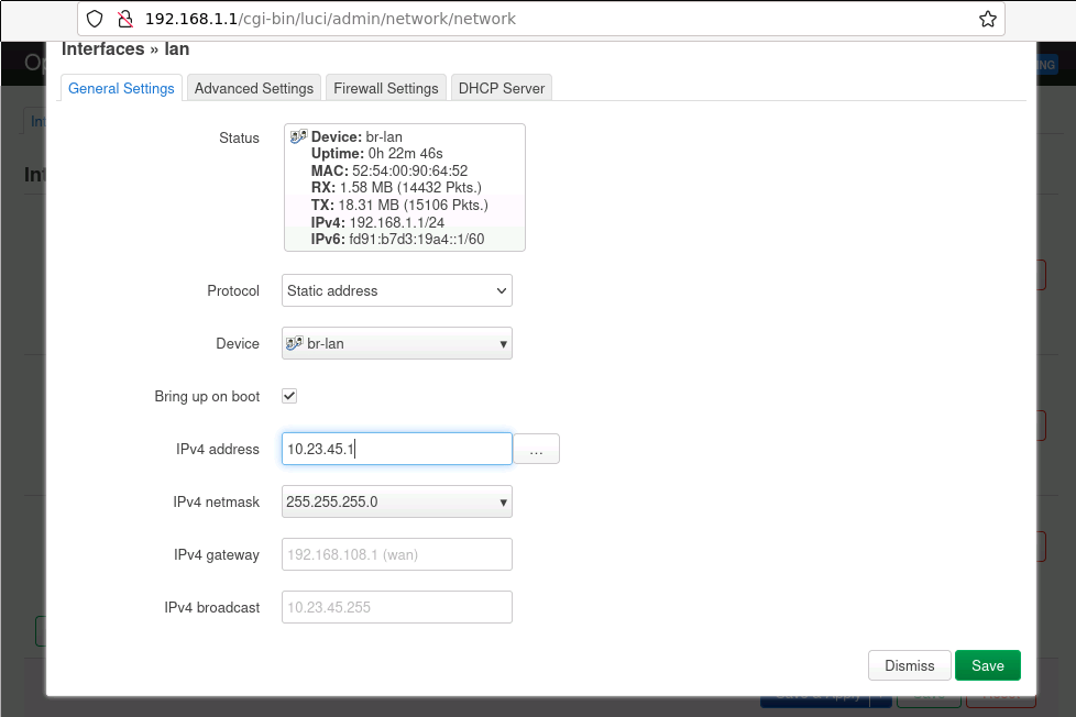
Go to the top “Network” menu and select “Interfaces”. Click “Edit” on the
laninterface. Set the network parameters for the private network as assigned by the lab instructor.
Save the new parameters. On the top right you will see a message “Unsaved changes: 2”. Click “Save and Apply”. We will lose connectivity since we are switching to a different network. You will get a warning. Click “Change and Apply Settings” and when you see the timer, close the web browser.
To recover connectivity, we need to reconfigure the client network parameters. On the terminal, first de-configure the network (release the previous lease):
user@server2:~$ sudo dhclient -r
While no IP address is assigned, start Wireshark on server2 and capture traffic on
enp7s0(no filters). Now request a new lease:user@server2:~$ sudo dhclient -v
Stop capturing traffic and analyze the dialog with the router. In particular, note DHCP, ICMP and ARP traffic. Explain the logic of the dialog. Note DHCP sequence: Discover, Offer, Request, ACK. There is also a ICMP echo request and an ARP dialog. Verify that the new assigned address is in the expected range.
Open the web browser again and check that the external router IP is still the same. Go back to the browser window in server2 and scroll down on the status page until you see the active DHCP leases. For server2, click the “Set static” button. This will ensure that the server always get the same IP address in the private network.
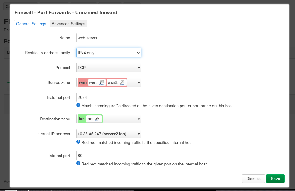
The private network behind our router is not accessible from the lab computer. For security reasons, the router GUI is also blocked on the external router interface (you may verify this using a browser on the windows computer). Now we’ll configure the router to make available the internal web server to the university network by forwarding a port from the external router interface to Port 80 (http) on server2. Go to the “Network” tab and select “Firewall”. Click on the “Port forwards” tab and then “Add”.
We’ll only allow connections using IPv4 with TCP (uncheck UDP, not used for http) from Port 2034 on the wan interface to Port 80 of server2 (you may choose a different external port). Make sure the internal IP address is set to the server2 address and the internal port is 80.

Check that the summary for the added port forwarding is correct. If so, press “Save and Apply”. After saving and applying the changes, the web server should be available from the Windows computer. The URL to connect from the Windows computer is
http://<router
IP>:<port number>/
(make sure you writehttp, nothttps). For our example, it ishttp://192.168.108.241:2034/. Note the addresses reported by the web server.Observe the NAT in action. Logout from the router interface and close the web browser in server2 (this is to reduce http traffic in the private network, to make easier the detection of the desired traffic).
Launch one instance of Wireshark on the Windows computer and in server2. First start capturing packets on both and then reload the web page on the Windows machine. After the page is reloaded stop capturing. Filter traffic using the “http” filter on both wireshark instances. Identify the packets with the same content on both instances and note the differences in IP addresses / port numbers.
Questions to be answered at the end of the Experiment
Show the network configuration at the web server to the lab instructor (
ip -4 a show).Explain the steps observed during the DHCP dialog. What is the purpose of the ICMP echo request? What is the purpose of the ARP from the router?
Show the web page on the Windows web browser and explain how everything works and the values presented there.
Show the captured traffic in both Wireshark instances and answer the following questions:
What IP address and port numbers are changed for traffic going from the Windows station to the web server? Source or destination?
What IP address and port numbers are changed for traffic going from the web server to the Windows station?