Experiment 3: IP Sub-networks and Static Router Configuration
Objectives
Setup an isolated network with 2 LANs. Determine network parameters for hosts in sub-networks.
Manually configure the network parameters for a client workstation, a router connecting the two LANs and a host for a web server.
Observe the traffic generated by the traceroute program to verify connectivity.
References
UltraVNC: https://uvnc.com/
Working with the linux command line: http://linuxcommand.org/lc3_learning_the_shell.php
Linux manual page: ip. You can read documentation about system commands by typing
man <command>in client1 or server2 (exit the man page by pressing ‘q’). The router has no manual pages installed.ip command overview and examples: https://www.cyberciti.biz/faq/linux-ip-command-examples-usage-syntax/
OpenWrt documentation: https://openwrt.org/docs/start
Wireshark: https://www.wireshark.org/
Background
Before performing this experiment, review the following topics from class notes: Internet layers, IP addressing, IP routing, Ethernet network concepts, ICMP protocols.
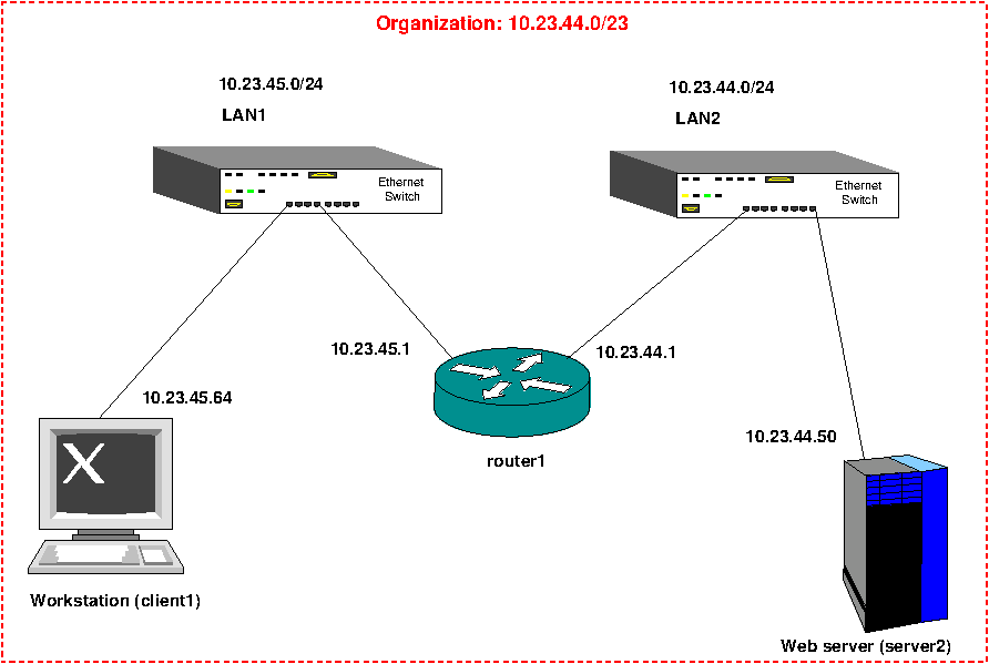
The network topology is shown below. Note that there is no external connection to Internet and that allows us to use any arbitrary addresses without interfering with the exterior world. IP addresses in the figure are just illustrative values: actual values for the experiment will depend on the group number and the organization ID assigned by the lab instructor. Note that the router has two IP addresses, one for each LAN.
Procedure
Ask the lab instructor to be assigned a group number (n), a virtual LAN network ID, and the port numbers to connect to the 3 virtual machines for this experiment. In this manual, we’ll assume that the data provided is the following:
Virtual LAN ID: 10.23.44.0/23
Port for client workstation (client1) in LAN1: 11000
Port for router: 11001
VNC password and account information for client1, router and server1
Port for web server in LAN2 (server2): 11002
Before you type anything on the computer, you must sub-divide the assigned LAN in two sub-networks, one for LAN1 and one for LAN2. Calculate the corresponding masks, which will be needed for the router configuration file and assign an IP address to all network interfaces (2 in the router and one on each station). Normally the router for a network is assigned the first few host addresses for the network. For example, if LAN1 was assigned
10.23.45.0/24for the network ID, you should configure the corresponding interface of your router at10.23.45.1, as shown in the diagram. It is recommended to draw your own diagram with the IP address for each interface to guide you during the configuration steps.Launch 3 UltraVNC instances, one for each of the 3 stations. The addresses to connect should look similar to the following:
2453server.lakeheadu.ca:11000
2453server.lakeheadu.ca:11001
2453server.lakeheadu.ca:11002
Begin by configuring the router first. This router firmware is configured by default to be used in embedded devices without a keyboard and a screen. As the router is not intended to run regular user applications, only basic utilities are available to reduce the memory requirements in embedded devices. Usually, the only way to access a command line is by using a remote computer connected to a network interface (using telnet or ssh), or using a serial terminal program. To simplify access for this experiment, we have enabled a virtual console, accessed through the VNC protocol. Press enter to start a shell in the console. A warning message will inform that there is no root password, which is not safe. For this experiment, the warning may be ignored as the networks are isolated. Run
ip -f inet addr show(or abbreviatedip -4 a show) to see IPv4 configured interfaces (assigned ip addressed may be different):# ip -4 a show 1: lo: <LOOPBACK,UP,LOWER_UP> mtu 65536 qdisc noqueue state UNKNOWN qlen 1000 inet 127.0.0.1/8 scope host lo valid_lft forever preferred_lft forever 3: eth1: <BROADCAST,MULTICAST,UP,LOWER_UP> mtu 1500 qdisc fq_codel state UP qlen 1000 inet 192.168.2.1/24 brd 192.168.2.255 scope global eth1 valid_lft forever preferred_lft forever 4: br-lan: <BROADCAST,MULTICAST,UP,LOWER_UP> mtu 1500 qdisc noqueue state UP qlen 1000 inet 10.168.1.129/25 brd 10.168.1.255 scope global br-lan valid_lft forever preferred_lft forever
The router has 4 network interfaces defined by default:
lo: is the loopback network interface, configured to 127.0.0.1/8. This is a special address that always points to the localhost (the router in this case).
eth0: connected to LAN1, part of a bridge (br-lan)
eth1: connected to LAN2
br-lan: is a virtual bridge that has eth0 as one of its ports. Since eth0 is included in the bridge, we’ll directly configure the br-lan device and ignore eth0. You may list the interfaces (there is only one by default) connected to this bridge by running the following command:
# brctl show br-lan
Initially, the router interfaces will be configured to some generic IP addresses. We will change these to the addresses assigned to the group. In OpenWrt, top-level configuration files are located in
/etc/config. the basic network parameters can be set by editing thenetworkfile. You may useviornanoto edit text files in the router. If you are not familiar with any of those, usenano, which is aimed at beginners:# nano /etc/config/networkYou only need to update the lan (br-lan interface) and wan (eth1) sections to reflect the network IP addresses and netmasks assigned to your group. In our example, the lan section is assigned 10.23.45.1 with a mask of 255.255.255.0, and the wan section to 10.23.44.1 with a similar mask:
config device
        option name 'br-lan'
        option type 'bridge'
        list ports 'eth0'

config interface 'lan'
        option device 'br-lan'
        option proto 'static'
        option ipaddr '10.23.45.1'
        option netmask '255.255.255.0'

config interface 'wan'
        option device 'eth1'
        option proto 'static'
        option ipaddr '10.23.44.1'
        option netmask '255.255.255.0'
The new router configuration can be activated by running the following command:
# /sbin/reload_configIf no errors occur, verify that the interfaces have been assigned the correct IP addresses:
# ip -4 address showInclude the output of this in your report (for example using a screen capture). Note: OpenWrt also includes the
ifconfigutility in the default setup, so you may also use that one if you prefer. For the purpose of this experiment, the router should be now ready.Configure the client. Log-in into client1 and open a terminal. The
ipcommand can be used to manually configure the network interface. Runip a show(without the -4)to see all interfaces:client1:~$ ip a show 1: lo: <LOOPBACK,UP,LOWER_UP> mtu 65536 qdisc noqueue state UNKNOWN group default qlen 1000 link/loopback 00:00:00:00:00:00 brd 00:00:00:00:00:00 inet 127.0.0.1/8 scope host lo valid_lft forever preferred_lft forever 2: enp1s0: <BROADCAST,MULTICAST,UP,LOWER_UP> mtu 1500 qdisc fq_codel state UP group default qlen 1000 link/ether 52:54:00:e0:36:eb brd ff:ff:ff:ff:ff:ffOnly the loopback interface is currently configured. The Ethernet interface is named enp1s0 (check the name you get, it may be different). There is no active connection to other computers in the network. We will use a static configuration. First, we must elevate the privileges to make system changes. This can be achieved using the
sudocommand. We will assign the IP address and add the route to the table directly from the command line usingipcommand. This is a good approach to change the network configuration on the fly, but keep in mind that the configuration is lost after a reboot. The first command configures the interface (enp1s0) using the default broadcast address but keeps it disabled, the second command enables the interface:client1:~$ sudo ip addr add <address/bits> broadcast + dev <interface> client1:~$ sudo ip link set <interface> up
Example for our sample assigned addresses:
client1:~$ sudo ip addr add 10.23.45.64/24 broadcast + dev enp1s0
Check the interfaces are properly configured using the
ip -4 a
show
command. If correct, you should be able to ping the router now:client1:~$ ping -c 3 10.23.45.1 PING 10.23.45.1 (10.23.45.1) 56(84) bytes of data. 64 bytes from 10.23.45.1: icmp_seq=1 ttl=64 time=0.107 ms 64 bytes from 10.23.45.1: icmp_seq=2 ttl=64 time=0.279 ms 64 bytes from 10.23.45.1: icmp_seq=3 ttl=64 time=0.432 ms --- 10.23.45.1 ping statistics --- 3 packets transmitted, 3 received, 0% packet loss, time 2094ms rtt min/avg/max/mdev = 0.107/0.272/0.432/0.134 ms
Print the client routing table:
client1:~$ ip route
As we are doing things manually, there should be no default route. Add the default route to point to the router, to forward any packets not in LAN1 to the router:
client1:~$ sudo ip route add default via <router IP>
Run again
ip routeto check the result. Include this routing table in your report. You can try pinging the other router IP address. It should work.Configure the web server. Repeat the same steps you used for the client, using the IP addresses in LAN2 instead of LAN1. Try pinging the client. It should be reachable.
Launch wireshark on the client and start capturing traffic on the Ethernet interface. Use the following command to trace the route from the client to the webserver:
client1:~$ traceroute <server2 IP>
After the route is printed, stop capturing packets in Wireshark. Examine the captured packets due to the traceroute command. Explain how this sequence of messages work, noting the TTL field in the outgoing packets and the type of ICMP messages received in your report.
You may now close wireshark, open a web browser in client1 and connect to the web server by using the following URL: http://<server2 IP>/. For our example, http://10.23.44.50/. Verify that the information given by the webserver is correct, and include a screen capture in your report.
After the experiment is finished, close all VNC clients.
Report preparation and questions
Prepare a formal report summarizing this experiment in pdf format and submit it to the lab instructor. Report writing rules:
One report per group
All students are responsible for the contents of the report, but one student in the group must coordinate, write and submit the report for the experiment.
Clearly state in the report cover the name of all students in the group and indicate who prepared the report
Include in your report a diagram of the network topology used in the experiment. Show network ID for each segment, IP address for each interface and routing table in each host.
Include outputs indicated in boldface in some of the steps.
- Use the packets captured with wireshark to explain how the
tracerouteprogram determines the route to a host.
Write comments conclusions about this experiment.